Position the mould
The loaded mould reaches the tilting station and aligns with the designed pickup points.
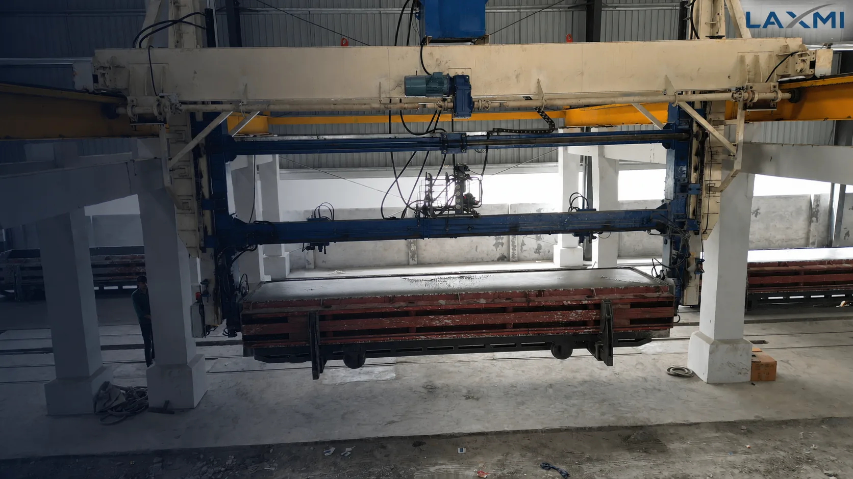
AAC MOULD & GREEN-CAKE HANDLING
A dedicated mould-handling and demoulding system engineered for controlled movement between pre-curing and wire cutting.
Final configuration depends on mould geometry, loaded weight, cutting arrangement and plant layout.
THE ENGINEERING PRINCIPLE
At the tilting stage, the AAC cake has developed enough green strength for handling, but it has not achieved finished-product strength.
Sudden acceleration, harsh braking, poor alignment or uneven mould release can contribute to cracks, damaged edges, deformation or complete cake failure. The machine must therefore coordinate load handling, mould release, cake support and cutting-line transfer as one controlled sequence.
WHY CONTROL MATTERS
The difference between a successful demoulding cycle and a damaged cake can begin with one uncontrolled movement.
Machine design is only one factor. Cake hardness, mix behaviour, temperature, mould condition and cutting readiness must also be evaluated.
OPERATING SEQUENCE
The detailed sequence varies between plant designs. A final proposal should document the actual machine configuration and its interfaces with mould circulation and cutting.
The loaded mould reaches the tilting station and aligns with the designed pickup points.
The handling device confirms engagement before the mould is lifted or rotated.
Acceleration and deceleration are managed through the movement, not only at the end positions.
The mould body is unlocked only after the required position and sequence conditions are confirmed.
The cake remains on, or transfers to, the support required by the configured cutting process.
The mould body and side plate return according to the plant's mould-circulation arrangement.
SELECT ON ENGINEERING INPUTS
A lifting-capacity figure alone cannot describe a tilting system. Selection begins with the mould, cake load, cutting process, building and required production rhythm.
Dimensions, lifting points and side-plate design define the handling interface.
The maximum loaded mould weight forms the basis for design load and component selection.
Target mould cycles must be defined together with travel distances and included movements.
Cake orientation, support and transfer sequence must match the selected cutting philosophy.
PROJECT-SPECIFIC DATA
Specifications should be issued after reviewing the actual interfaces. Project-dependent values must be presented with their assumptions—not as universal performance claims.
| Specification | Proposal requirement |
|---|---|
| Machine configuration | Offered arrangement, travel, operating sequence and cutting-line interface |
| Design and rated load | Working-load basis, component selection and agreed test requirement |
| Compatible mould range | Verified mould dimensions, pickup points and side-plate interface |
| Cycle definition | Start point, end point, included movements and stated operating conditions |
| Drive and control | Hoisting, tilting, locking, feedback devices and sequence-control scope |
| Project interfaces | Building clearances, runway loads, utilities and client-scope provisions |
CONTROL & FAULT RECOVERY
The final proposal should identify the interlocks that prevent lifting, tilting or mould release in an incorrect position. It should also explain emergency stopping, controlled restart and power-failure recovery.
Exact devices, logic and applicable design standards must be confirmed for the offered configuration.
THE COMMERCIAL CONSEQUENCE
A waiting cake continues to harden. A prolonged interruption may change cutting behaviour or make the cake unsuitable for normal wire cutting.
The result depends on recipe, cake condition, temperature, delay duration and cutting capability. Fault recovery, maintenance ownership and critical spare planning are therefore part of production-risk management.
EVALUATE THE COMPLETE SCOPE
Two quotations can use the same product name while carrying very different engineering, control, installation and acceptance responsibilities.
SYSTEM-LEVEL ENGINEERING
Laxmi En-Fab approaches the tilting machine as the connection between pre-curing, mould circulation, demoulding and cutting—not as an isolated lifting device.
Before a final technical proposal, the project inputs should be reviewed and the offered configuration, interfaces, sequence, testing and acceptance criteria should be documented.
Prepare your project inputsBUYER QUESTIONS
The terms are often used interchangeably. For procurement, the important question is the offered function: lifting, tilting, mould release, cake support, transfer, control and cutting-line integration.
Possible causes include unsuitable green strength, sudden movement, misalignment, uneven mould release, mould condition, release preparation and cutting-process issues. Machine and process conditions should be diagnosed together.
Many systems rotate the loaded mould by approximately 90 degrees, but the final movement and cake orientation depend on the plant configuration. The offered angle and sequence should be confirmed in the technical proposal.
Cycle time is meaningful only when the start and end points, travel distances, load, locking sequence, operating mode and surrounding line arrangement are stated.
Yes, subject to an engineering survey. Existing moulds, side plates, rails, building clearances, structural capacity, cutting interfaces and controls must be verified before finalisation.
Provide mould dimensions and type, maximum loaded weight, target cycles, cutting arrangement, building information, automation requirement, project location and whether the requirement is new-build or retrofit.
CONFIGURATION BEFORE QUOTATION
Share your mould dimensions, maximum loaded weight, target mould cycles, project location and cutting-line arrangement. The review can identify the required machine configuration and project interfaces.